
![]()
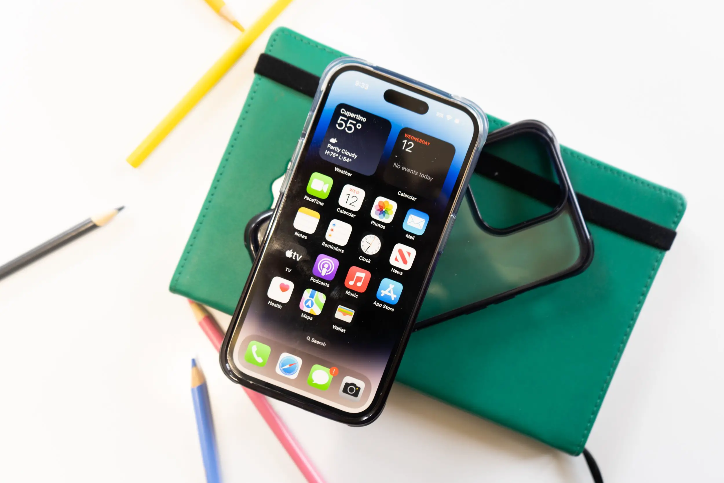
AT&T won’t sit back while their competitors bring 4G LTE to anyone and everyone they can. The company may not be making huge strides but progress is progress, and we have even more of that progress today. They have lit up Tampa, Florida and Raleigh, North Carolina with sweet, blazing fast 4G LTE. Surrounding markets will also benefit from the new rollouts, too, with coverage stretching to Durham, NC, Manatee, FL and more. Go outside and celebrate by downloading something – ANYTHING!


but if they go download something it will put them in the top %5. lol at AT&T
WE ARE THE 5%
My rebuttal:
I’ll begin with a brief discussion on the evolution of mobile communications
networks, followed by introduction to cellular concept. Then we discuss the concepts of
frequency reuse, handoff and trunking. This is followed by a discussion on interference and
system capacity where we calculate the co-channel interference using a geometric model. Then we discuss techniques to increase the system capacity. Finally we discuss the current and future architectures for wireless networks.
Evolution of Mobile Communications
The objective of early land to mobile radio systems was to achieve a large coverage area by
using a single, high powered transmitter with an antenna mounted on a tall tower[1]. This was
done by selecting several channels from a specific frequency allocation for use in autonomous
geographic zones. The communications coverage area of each zone was usually planned to be
as large as possible. The number of channels that could be obtained from the allocated spectrum
was limited. There was generally no in system interference as the same frequencies were reused
in the next service area which used to be several hundred miles away.
Some of the drawbacks of the early land to mobile systems were limited service capability, high
blocking probabilities, inefficient frequency spectrum utilization. If there were two contiguous
service areas then call had to be terminated and reinitiated in the next service area. There was
no concept of handoff. In addition to this, the regulatory agencies could not make spectrum
allocations in proportion to the increasing demand for mobile services, thus making it
imperative to restructure the mobile radio system to achieve high capacity with limited radio
spectrum, while at the same time covering very large areas.7
Large scale integrated circuit technology reduced the size of mobile transceivers to one that
could easily fit into the standard automobile. Another factor was the reduction in price of the
mobile telephone unit. Technology, feasibility and service affordability caused the transition
from early land to mobile systems to the cellular systems.
Mobile communications is currently at its fastest growth period in history, due to enabling
technologies which permit wide spread deployment. Historically, growth in the mobile
communications field has come slowly, and has been linked to technological advancements. The
ability to provide wireless communications to an entire population was first conceived when
Bell Laboratories developed the cellular concept in the 1960s and 1970s. The tremendous
growth in the mobile communications is primarily due to development of highly reliable,
miniature solid state devices and the development of the cellular concept. The future growth of
consumer-based mobile and portable communication systems will depend on radio spectrum
allocations, regulatory decisions, adoption of common standards, consumer needs and
technology advances in the signal processing, access, and integration of voice and data
networks.
Examples of Mobile Radio Systems
Some common examples of other mobile radio communication systems are garage openers,
remote controllers for home entertainment equipment, cordless telephones, hand-held walkietalkies, pagers and wireless LANs. We will discuss briefly the paging systems and the cordless
telephone system below:
Paging systems are communication systems that send brief messages to a subscriber. The
message may be either a numeric message, an alphanumeric message, or a voice message
depending on the service available. In modern paging systems, news headlines, stock
quotations, faxes and emails may be sent. A message is sent to a paging subscriber via the
paging system access number or through the Internet. The paging system then transmits the8
page throughout the service area using base stations which broadcast the page on a radio
carrier. The paging systems usually have large transmitter powers and use low data rates to
achieve maximum coverage from each base station with minimum signal to noise requirement.
Recent paging systems allow two way paging in which the subscribers can send a pre-defined
set of messages.
Cordless telephone systems are full duplex communication systems that use a radio to connect a
portable handset to a dedicated base station, which is then connected to a dedicated telephone
line with a specific telephone number on the public switched telephone network (PSTN). The
portable unit communicates only to the dedicated base unit and only over distances of a few
tens of meters. Cordless telephone systems provide the user with limited range and mobility.
The Cellular Concept
The cellular concept was a major breakthrough in solving the problem of spectral congestion
and user capacity. It offered high capacity with a limited spectrum allocation without any major
technological changes. The cellular concept is a system level idea in which a single, high power
transmitter (large cell) is replaced with many low power transmitters (small cells). The area
serviced by a transmitter is called a cell. Each small powered transmitter, also called a base
station provides coverage to only a small portion of the service area. Base stations close to one
another are assigned different groups of channels so that all the available channels are assigned
to a relatively small number of neighboring base stations. Neighboring base stations are
assigned different groups of channels so that the interference between base stations is
minimized. By symmetrically spacing base stations and their channel groups throughout a
service area, the available channels are distributed throughout the geographic region and may be
reused as many times as necessary, so long as the interference between co-channel stations is
kept below acceptable levels.9
As the demand for service increases, the number of base stations may be increased, thereby
providing additional capacity with no increase in radio spectrum. This fundamental principle is
the foundation for modern mobile communication systems, since it enables a fixed number of
channels to serve an arbitrarily large number of subscribers by reusing the channels throughout
the region. The concepts of frequency reuse, handoff and system capacity are explained below.
1. 3 Frequency Reuse
The base station antennas are designed to achieve the desired coverage within the particular
cell. By limiting the coverage area to within the boundaries of a cell, the same group of channels
may be used to cover different cells that are separated from one another by distances large
enough to keep interference levels within tolerable limits. The design process of selecting and
allocating channel groups for all the cellular base stations within a system is called frequency
reuse or frequency planning.
In Fig. 1.1 the cells labeled with the same letter use the same group of channels. The frequency
reuse plan is overlaid upon a map to indicate where different frequency channels are used. The
hexagonal cell shape shown is conceptual and is a simplistic model of the coverage for each
base station. The hexagon has been universally adopted since the hexagon permits easy and
manageable analysis of a cellular system. Also considering geometric shapes which cover an
entire region without overlap and with equal area, hexagon has the largest area considering the
distance between the center of a polygon and its farthest perimeter points. The actual footprint
is determined by the contour in which a given transmitter serves the mobiles successfully.10
Diagram of cellular frequency reuse. Cell with the same letter use the same set of
frequencies. The reuse shown here is for a cluster size of N = 7.
1.4 Concept of Handoff
When a mobile moves into a different cell while a call is in progress, the mobile switching center
(MSC) automatically transfers the call to a new channel belonging to the new base station. This
handoff operation involves identifying a new base station, assigning a free channel in the new
cell to the mobile to change the frequency and transfer the voice circuit to the new base station.
Processing handoffs is an important task in any cellular radio system. The handoff process can
be performed based on several criteria such as signal strength, bit error rate in digital systems or
interference levels. For example, if the signal level is used to trigger the handoff, an optimum
signal level at which to initiate handoff is specified which approximately corresponds to the
boundary of the cell. Once particular signal level goes below the specified threshold the base11
station queries the received power from the mobile at the different neighboring base stations,
and picks a base station which has a power higher than that seen in the serving base station by a
specified margin. Also in deciding when to handoff, it is important to ensure that the drop in the
measured signal level is not due to momentary fading and that the mobile is actually moving
away from the serving base station. In order to ensure this, the base station monitors the signal
level for a certain period of time before a hand-off is initiated. This running average
measurement of signal strength should be optimized so that unnecessary handoffs are avoided,
while ensuring that necessary handoffs are completed before a call is terminated due to poor
signal level.
1.5 Concept of Trunking
Cellular systems depend on trunking to accommodate a large number of subscribers in a limited
number of channels. The concept of trunking allows a large number of users to share a
relatively small number of channels by providing access to each user, on demand, from a pool of
available channels. In a trunked system, each user is assigned a channel on a per call basis, and
upon termination of the call, the previously occupied channel is immediately returned to the
pool of available channels. Trunking exploits the statistical behavior of users so that a fixed
number of channels or circuits may accommodate a large number of users. The grade of service
(GOS) is a measure of the ability of a user to access a trunked system during the busiest hour of
call traffic. It is clear that there is a trade-off between the number of available channels and the
likelihood of a particular user finding that no channels are available during the peak calling time.
The number of channels required is determined based the number of subscribers, desired GOS,
average call holding time and traffic distribution with time.12
1.6 Interference and System Capacity
Interference is the limiting factor in the performance of cellular systems[4,5]. Sources of
interference include another mobile in the same cell, a call in progress in a neighboring cell,
other base stations operating in the same frequency band, or any non cellular system which
inadvertently leaks energy into the cellular frequency band. Interference on voice channels
causes background noise and results in poor voice quality. On control channels, interference
leads to missed and blocked calls due to errors in the digital signaling. Interference is the major
bottleneck in increasing capacity of a cellular network. The major types of system generated
cellular interference are co-channel interference and adjacent channel interference. Here we will
consider in-band interference only i.e., the interference caused by other cellular users.
Co-Channel Interference and System Capacity
Cells in a given coverage area that use the same set of frequencies are called co-channel cells
and the interference between signals from these cells is so called co-channel interference. The
co-channel interference cannot be reduced by increasing the carrier power of a transmitter,
since an increase in carrier transmit power also increases the interference power to neighboring
co-channel cells, thus keeping the carrier to interference ratio constant. If we assume base
stations with omni antenna systems with no power control, the only way to reduce the cochannel interference is to increase the physical distance between the co-channel cells to provide
sufficient isolation due to propagation loss.
In a cellular system, where the size of each cell is the same, co-channel interference is
independent of the transmitted power. The co-channel interference is only a function of the
ratio of radius of the cell R, and the distance to the center of the nearest co-channel cell D.
Increasing the ratio of D/R, the spatial separation between co-channel cells relative to the
coverage distance of a cell increases the carrier to the interference ratio. The parameter Q,
called the co-channel reuse ratio is related to the cluster size N for hexagonal geometry by
A small value of Q provides larger capacity since the cluster size is small but increases the
interference, whereas a large value of Q provides lesser capacity but reduces the co-channel
interference.
Cluster Size Co-channel Reuse ratio (Q)
Table 1.1 Co-channel Reuse Ratio for some values of N
Let io
be the number of co-channel interfering cells. Then, the carrier to interference ratio C/I
for a mobile receiver which monitors a forward channel can be expressed as
where C is the desired carrier power from the desired base station and I
i
is the interference
power caused by the i th interfering co-channel cell base station. If the signal levels of cochannel cells are known, then the C/I ratio for the forward link can be found using (1.2).
Propagation measurements in a mobile radio channel indicate that the average received signal
strength at any point decays as a power law of the distance of separation between a transmitter
and receiver. The average power Pr
at a distance d from the transmitting antenna is
approximated by14
where Po
is the power received at a close in reference point in the far field region of the
antenna at a small distance do
from the transmitting antenna, and n is the path loss exponent.
Consider the forward link where the mobile is at a distance R from the serving base station and
where the interference is due to co-channel base stations. If Di
is the distance of the i th
interferer from the mobile, the received power at a mobile due to the i th interfering cell will be
proportional to ( ) Di
−n
. The path loss exponent typically ranges between 2 and 4 in frequency
ranges being used for cellular systems.
When the transmit power of each base station is equal and the path loss exponent is the same
throughout the coverage area, C/I for a mobile can be approximated as
Considering only the first tier of interfering cells, if all the interfering base stations are
equidistant from the desired base station and if this distance is equal to the distance D between
cell centers, then equation (1.4) simplifies to
This gives the relation between the C/I to the cluster size N, which in turn
determines the overall capacity of the system. For AMPS systems, typically a C/I of 17 dB is
needed to provide an acceptable voice quality. Assuming a path loss exponent of 4, a minimum15
cluster size of 7 is required to meet a C/I requirement of 18 dB. This result is based on
geometry and does not take into account the shadowing characteristics of the propagation
environment and is thus optimistic.
In Figure 1.2 it can be seen that for an N = 7 cell cluster, with the mobile unit at the cell
boundary, the mobile is a distance D-R from the two nearest co-channel interfering cells and
approximately D + R/2 , D, D-R/2, and D+R from the other interfering cells in the first tier.
Using equation (1.5) and assuming n equals 4, the signal to interference ratio for the worst case
can be closely approximated as
This expression can be used to calculate the carrier to interference ratio geometrically for
different cluster sizes.
Diagrams will show the first tier of cells for a cluster size of N=7. Also shown are
the distances from a mobile at the edge of a cell to the base stations in co-channel cells.
1.7 Increasing the System Capacity
Different techniques such as cell splitting, sectoring, cell tiering, power control and smart
antennas can be used to increase the system capacity. We will briefly discuss some of these
techniques.17
Cell splitting
Cell splitting is the process of subdividing a congested cell into smaller cells, each with its own
base station and a corresponding reduction in antenna height and transmitter power. Cell
splitting increases the capacity of a cellular system since it increases the number of times that
channels are reused. By making these the new cells to have smaller radius than the original cells
and by installing these smaller cells between the existing cells, capacity increases due to the
additional number of channels per unit area. Cell splitting achieves capacity improvement by
essentially re-scaling the system. By decreasing the radius R and keeping the co-channel reuse
ratio D/R unchanged, cell splitting increases the number of channels per unit area.
Sectoring
Sectoring is another way to increase capacity. In this approach, capacity improvement is
achieved by reducing the number of cells in a cluster and thus increasing the frequency reuse.
The co-channel interference in a cellular system may be decreased by replacing a single omni
directional antenna at the base station by several directional antennas, each radiating within a
specified sector. By using directional antennas, a given cell will receive interference and
transmit with only a fraction of the available co-channel cells. The technique for decreasing cochannel interference and thus increasing system capacity by using directional antennas is called
sectoring.
A cell is usually sectored into three sectored or six sectored configurations. When sectoring is
employed, the channels used in a particular cell are broken down into sectored groups and are
used only within a particular sector, as shown in the figure. Assuming a 7 cell reuse of the case
of 120 degree sectors, the number of interferers in the first tier is reduced from 6 to 2. This is
because only 2 of the 6 co-channel cells receive interference with a particular sectored channel
group. The resulting C/I for this case can be found using equation (1.4) to be 24.2 dB, which is
a significant improvement over the omni-directional case, where the worst case C/I was 17 dB.18
Cell Tiering
Dividing the cell into two tiers and reusing frequencies intelligently such that the frequencies
used in the outer tier in the serving cell are used in the inner tier in the co-channel cells
increases the C/I ratio. The channel set allocated to each site is divided into two groups. The
maximum transmit power for the inner tier channels is set so that signal level hits the threshold
at the tier boundary. Handoff process takes place at the tier boundary.
The reduction in interference offered by sectoring and tiering enable planners to reduce the
cluster size N, and provides an additional degree of freedom in assigning channels. The penalty
for improved C/I is an increased number of antennas, a decrease in the trunking efficiency due
to channel sectoring at the base station and an increase in processing due to handoff activity
between sectors and tiers.
Power Control
Controlling the transmit power of the mobile and base station reduces the system interference
and thus can be used to reduce the cluster size if implemented properly. In practical cellular
radio and personal communication systems the power levels transmitted by every subscriber
unit are under constant control by the serving base stations. This is done to ensure that each
mobile transmits the smallest power necessary to maintain a good quality link on the reverse
channel. Power control not only helps prolong battery life for the subscriber unit, but also
dramatically reduces the reverse channel C/I in the system.
Further improvements in C/I is achieved by down-tilting the antenna such that the radiation
pattern is the vertical plane has a notch pointing at the nearest co-channel cell. Also other
techniques such as use of smart antennas, and co-channel interference cancellation algorithms
can be used to improve the C/I. In practical high capacity systems all the above mentioned
techniques are used together in dense urban environments to achieve high system capacity.19
1.8 Architecture and development of Wireless Networks
The early version of analog cellular networks are called as first generation networks. The
current digital cellular networks are called second generation networks and the future cellular
networks under development are called third generation networks.
First Generation Wireless Networks
All first generation cellular networks are based on analog technology and use FM modulation.
An example of the first generation cellular telephone system is Advanced Mobile Phone
Services (AMPS)[3].
Block diagram of the first generation cellular network.
The block diagram of a first generation cellular radio network architecture is shown in which includes the mobile terminals, the base station and the mobile switching center
(MSC). In The control for entire system resides in the MSC, which maintains all mobile related
information and controls each mobile hand-off. The MSC also performs all, of the network
management functions, such as call handling and processing, billing, and fraud detection within
the market. The MSC is interconnected with the public switched telephone network (PSTN) via
land-line trunked lines (trunks) and a tandem switch. MSC’s also are connected with other20
MSCs via dedicated signaling channels for exchange of location, validation, and call signaling
information.
PSTN is a separate network from the SS7 signaling network. In modern cellular telephone
systems, long distance voice traffic is carried on the PSTN, but the signaling information used
to provide call set-up and to information used to provide call set-up and inform MSCs about a
particular user is carried on the SS7 network.
Network protocol standard like IS-41 allows different cellular systems to automatically
accommodate subscribers who roam into their coverage region. IS-41 allows MSCs of different
service providers to pass information about their subscribers to other MSCs on demand. IS-41
relies on autonomous registration. The mobile accomplishes autonomous registration by
periodically keying up and transmitting its identity information, which allows the MSC to
constantly update its subscriber list. The MSC can distinguish home users from roaming users
based on the mobile identification number (MIN) of each active user, and maintains a real time
user list of home location register (HLR) and visitor location register (VLR). IS-41 allows the
MSCs of neighboring systems to automatically handle the registration and location validation of
roamers so that users no longer need to manually register as they travel. The visited system
creates VLR record for each new roamer and notifies the home system via IS-41 so it can
update its own HLR.
Second Generation Wireless Networks
Second generation wireless systems employ digital modulation and advanced call processing
capabilities. Examples of second generation wireless systems include the Global System for
Mobile (GSM), the IS-54 TDMA and the IS-95 CDMA TIA digital standards.
Second generation wireless networks have introduced new network architectures that have
reduced the computational burden of the MSC. The GSM has introduced the concept of a base21
station controller (BSC) which is inserted between the several base stations and the MSC. This
architectural change has allowed the data interface between the base station controller and the
MSC to be standardized, thereby allowing carriers to use different manufacturers for MSC and
BSC components.
All second generation systems use digital voice coding and digital modulation. Second
generation systems also provide dedicated voice and signaling trunks between MSCs, and
between each MSC and PSTN. The second generation systems in addition to voice also provide
paging, and other data services. The network controlling structure is more distributed in the
second generation wireless systems, since mobile stations assume greater control functions. In
second generation wireless networks, the handoff process can use mobile-assisted handoff
(MAHO) in which the mobile sends the reading of receive signal strength or bit error rate based
on the forward link. The mobile units in these networks perform several other functions not
performed by first generation subscriber units, such as received power reporting, adjacent base
station scanning, data encoding, and encryption.
Third Generation Wireless Networks
Third generation wireless systems will evolve from mature second generation systems. The aim
of third generation wireless networks is to provide a single system that can meet a wide range
of applications and provide universal access. The third generation networks will carry many
types of information such as voice , data and video and serve both stationary and fixed users.
Some of the systems proposed for the third generation systems are CDMA2000 which is
backward compatible to systems based on IS 95 and WCDMA which is backward compatible
to GSM systems.
Read the whole thing. O_o
Good, God Chris looks like you guys should hire the guy, below you who posted a whole book on here…alol.
Cool. At this rate we will have ATT LTE in about 6 years. Maybe that will give them time to finish rolling our 3G.
Verizon just expanded their 4g coverage and set up five new towers as opposed to two from AT&T…why was this not reported on?